High Pressure Full Welded Ball Valve for Oil & Gas
BAL702
Product Description
IFLOW high pressure fully welded ball valves for offshore applications are top solutions for the oil and gas industry. Crafted using precision engineering and cutting-edge technology, the valve is designed to withstand extreme conditions and provide unparalleled performance in offshore environments. It is constructed with high-strength materials and a fully welded body for exceptional durability and reliability, making it ideal for offshore operations.
The valve is equipped with an advanced sealing mechanism that ensures tight closure and minimal leakage, thereby enhancing the safety and environmental protection of offshore installations. Its rugged design and high-pressure capabilities make it suitable for critical applications, providing seamless flow control and optimal performance under high-pressure conditions. Fully welded construction eliminates potential leak points, giving you peace of mind and ensuring the integrity of offshore oil and gas systems.
IFLOW’s high-pressure fully welded ball valves are designed to meet industry standards and regulatory requirements, ensuring compliance and reliability in offshore operations. Its compact design and efficient installation features make it a cost-effective and low-maintenance solution for offshore installations. Choose IFLOW’s high-pressure fully welded ball valves for offshore applications and experience superior quality, durability and performance in the most demanding offshore environments.
Features
Product Overview
The range can be engineered to suit your application, with body construction, material, and ancillary features optimised to meet your process needs. Being ISO 9023 certified, we adopt systematic ways to ensure high quality, you can be assured of outstanding reliability and sealing performance through the design life of your asset.


Technical Requirement
· Working Pressure: PN20
· Working Temperature: -10℃~170℃
· WORKING MEDIUM: Water, Oil and Steam
Specification
Product wireframe

Dimensions Data
Specification
| Nominal diameter(in) | NPS6-40 | ||||||
| Nominal pressure(Mpa) | Class150-Class900 | ||||||
| NO | PART NAME | CARBON STEEL | STAINESS STELL | ||||
| Material of parts | 1 | Body | ASTMA105 | ASTMA182 304 | ASTMA182 316 | ASTMA182 304L | ASTM A182 316L |
| 2 | Anti-fire packing | Graphite | |||||
| 3 | Seat | PTFE/NYLON/PEEK/PPL | |||||
| 4 | Seat ring | ASTM A105.ENP | ASTMA182 304 | ASTMA182 316 | ASTMA182 304L | ASTM A182 316L | |
| 5 | O-ring | VITON | |||||
| 6 | Spring | 17-7PH | |||||
| 7 | Bonnet | ASTMA105 | ASTMA182 304 | ASTMA182 316 | ASTMA182 304L | ASTM A182 316L | |
| 8 | Sealant injection valve | Combined parts | Combined parts | Combined parts | Combined parts | Combined parts | |
| 9 | Check valve | Combined parts | Combined parts | Combined parts | Combined parts | Combined parts | |
| 10 | Ball | ASTM A105.ENP | ASTMA182 304 | ASTMA182 316 | ASTMA182 304L | ASTM A182 316L | |
| 11 | Thrust gasket | PTFE | |||||
| 12 | Sliding bearing | Metal+PTFE | Metal+PTFE | Metal+PTFE | Metal+PTFE | Metal+PTFE | |
| 13 | Pin | ANSI 1035 | ANSI 1035 | ANSI 1035 | ANSI 1035 | ANSI 1035 | |
| 14 | Bearing holder | ASTM A105.ENP | ASTMA182 304 | ASTMA182 316 | ASTMA182 304L | ASTM A182 316L | |
| 15 | Seal gland | ASTM A105.ENP | ASTMA182 304 | ASTMA182 316 | ASTMA182 304L | ASTM A182 316L | |
| 16 | Thrust bearing | PTFE | |||||
| 17 | Stem | ASTM A 182 F6a | ASTM A182 304 | ASTMA182 316 | ASTMA182 304L | ASTM A182 316L | |
| 18 | Flat key | ANSI 1045 | ANSI 1045 | ANSI 1045 | ANSI 1045 | ANSI 1045 | |
| 19 | Thrust bearing | PTFE | |||||
| 20 | Anti-fire gasket | SST+Graphite | |||||
| 21 | Connection plate | ASTMA105 | ASTMA182 304 | ASTMA182 316 | ASTMA182 304L | ASTM A182 316L | |
| 22 | Socket head cap screw | A193 B7M | A320 B8 | A320 B8M | A320 B8 | A320 B8M | |
| 23 | Packing | Graphite | |||||
| 24 | Packing gland | ASTM A 182 F6a | ASTM A 182 F6a | ASTM A 182 F6a | ASTM A 182 F6a | ASTM A 182 F6a | |
| 25 | Anti-static valve | Combined parts | Combined parts | Combined parts | Combined parts | Combined parts | |
| 26 | Air release valve | Combined parts | Combined parts | Combined parts | Combined parts | Combined parts | |
| 27 | Drainage valve | Combined parts | Combined parts | Combined parts | Combined parts | Combined parts | |
| Applicalbe service conditions | Applicable media | Water steam,oil,gas,liquefed,gas,natural gas,etc | Nitric acidAcetic acid | Acetic acid | Strong Oxidizer | Urea | |
| Applicalbe temperature | 120℃(PTFE).≤80℃(NYLON),≤250℃(PEEK), ≤250℃(PPL) | ||||||
| Design and manufacturing | API 608,API6D | ||||||
| Face-to face dimensions | ASME B16.10, API 6D,JIS B2002 | ||||||
| Type of connection | Flange | ASME B16.5/ASME B16.47 | Bult welding | ASME B16.25 | |||
| Pressure test | API598. API6D | ||||||
| Transmission mode | Manual, worm and worm gear transmission, pneumatic, electric | ||||||
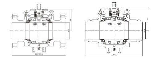
Dimensions data(mm)
| Pressure rating | Nominal Diameter | d | Flange | Bult welding | H | Weight(kg) | |||
| Class | NPS | DN | L(RF) | L(RTJ) | L(BW) | WE | RF | ||
| 150 | 6″ | 150 | 150 | 394 | 406 | 457 | 225 | 185 | 220 |
| 8″ | 200 | 201 | 457 | 470 | 521 | 258 | 250 | 290 | |
| 10″ | 250 | 252 | 533 | 546 | 559 | 310 | 400 | 430 | |
| 12″ | 300 | 303 | 610 | 622 | 635 | 350 | 550 | 620 | |
| 14″ | 350 | 334 | 686 | 699 | 762 | 382 | 820 | 900 | |
| 16″ | 400 | 385 | 762 | 775 | 838 | 421 | 1100 | 1220 | |
| 18″ | 450 | 436 | 864 | 876 | 914 | 468 | 1400 | 1550 | |
| 20″ | 500 | 487 | 914 | 927 | 991 | 510 | 1750 | 1950 | |
| 24″ | 600 | 589 | 1067 | 1080 | 1143 | 592 | 2800 | 3050 | |
| 26″ | 650 | 633 | 1143 | / | 1245 | 635 | 2900 | 3250 | |
| 28″ | 700 | 684 | 1245 | / | 1346 | 675 | 3400 | 3700 | |
| 30″ | 750 | 735 | 1295 | / | 1387 | 723 | 4800 | 5300 | |
| 32″ | 800 | 779 | 1372 | / | 1524 | 751 | 5500 | 6000 | |
| 36″ | 900 | 874 | 1524 | / | 1727 | 858 | 7550 | 8370 | |
| 40″ | 1000 | 976 | 1753 | / | 1956 | 930 | 10290 | 11320 | |
| 300 | 6″ | 150 | 150 | 403 | 419 | 457 | 225 | 185 | 230 |
| 8″ | 200 | 201 | 502 | 518 | 521 | 258 | 250 | 300 | |
| 10″ | 250 | 252 | 568 | 584 | 559 | 310 | 400 | 460 | |
| 12″ | 300 | 303 | 648 | 664 | 635 | 350 | 550 | 670 | |
| 14″ | 350 | 334 | 762 | 778 | 762 | 382 | 820 | 1000 | |
| 16″ | 400 | 385 | 838 | 854 | 838 | 421 | 1100 | 1320 | |
| 18″ | 450 | 436 | 914 | 930 | 914 | 468 | 1400 | 1650 | |
| 20″ | 500 | 487 | 991 | 1010 | 991 | 510 | 1750 | 2000 | |
| 24″ | 600 | 589 | 1143 | 1165 | 1143 | 592 | 2800 | 2550 | |
| 26″ | 650 | 633 | 1245 | / | 1245 | 635 | 2900 | 3300 | |
| 28″ | 700 | 684 | 1346 | / | 1346 | 675 | 3400 | 3750 | |
| 30″ | 750 | 735 | 1397 | / | 1397 | 723 | 4800 | 5500 | |
| 32″ | 800 | 779 | 1524 | / | 1524 | 751 | 5500 | 6500 | |
| 36″ | 900 | 874 | 1727 | / | 1727 | 858 | 7550 | 8800 | |
| 40″ | 1000 | 976 | 1956 | / | 1956 | 930 | 10290 | 11900 | |
| Pressure rating | Nominal Diameter | d | Flange | Bult welding | General | Weight(kg) | |||
| Class | NPS | DN | L(RF) | L(RTJ) | L(BW) | H | WE | RF | |
| 600 | 6″ | 150 | 150 | 559 | 562 | 559 | 255 | 250 | 330 |
| 8″ | 200 | 201 | 660 | 664 | 660 | 290 | 340 | 450 | |
| 10″ | 250 | 252 | 787 | 791 | 787 | 320 | 570 | 710 | |
| 12″ | 300 | 303 | 838 | 841 | 838 | 380 | 580 | 1000 | |
| 14″ | 350 | 334 | 889 | 892 | 889 | 410 | 1100 | 1370 | |
| 16″ | 400 | 385 | 991 | 994 | 991 | 435 | 1350 | 1650 | |


