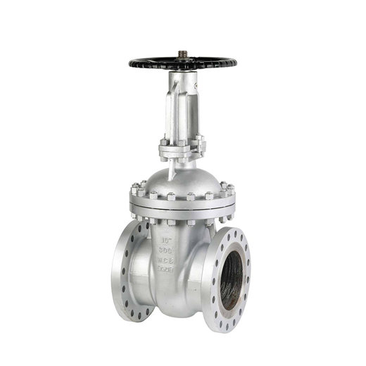
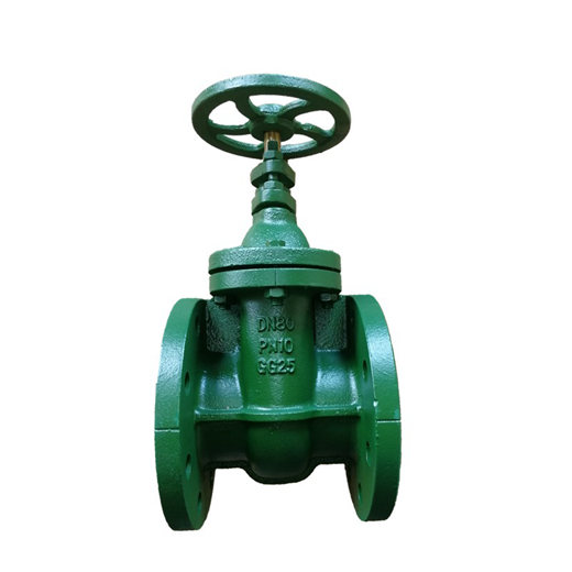
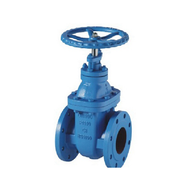
API600 Class 300 OS&Y Cast Steel Gate Valve
GAV701-300
Product Description
IFLOW API600 Class 300 OS&Y cast steel gate valve, designed for marine and offshore applications. This high-quality gate valve offers numerous advantages and is suitable for the demanding conditions of marine and offshore environments. Made from high-quality cast steel, this gate valve offers exceptional strength and corrosion resistance, ensuring reliability and longevity in marine and offshore operations.
The external screw and yoke (OS&Y) design provides clear visual indication of valve position and ease of maintenance, which is critical for offshore installations. Featuring a Class 300 pressure rating, this gate valve is designed to withstand high pressure applications with precision and control, making it a reliable choice for marine and offshore systems. Its superior flow control capabilities ensure efficient and safe operation of critical ship and offshore processes.
Features
Product Overview
IFLOW API600 Class 300 OS&Y cast steel gate valves are the preferred solution to marine and offshore challenges, offering rugged construction, precise control and long-term reliability. Elevate your marine and offshore operations with this superior gate valve designed to perform in the most demanding environments.


Technical Requirement
· Design and Manufacture Conform to API 600
· Flange dimensions Conform to ASME B16.5
· Face to Face dimensions Conform to ASME B16.10
· Testing Conform to API 598
· Driving mode: hand wheel, bevel gear, electric
Specification
| Part Name | Material |
| Body | A216-WCB |
| Wedge | A216-WCB+CR13 |
| Bonnet Stud Nut | A194-2H |
| Bonnet Stud | A193-B7 |
| Stem | A182-F6a |
| Bonnet | A216-WCB |
| Stem Back Seat | A276-420 |
| Eyebolt pin | Carbon Steel |
| Handwheel | Ductile Iron |
Product wireframe
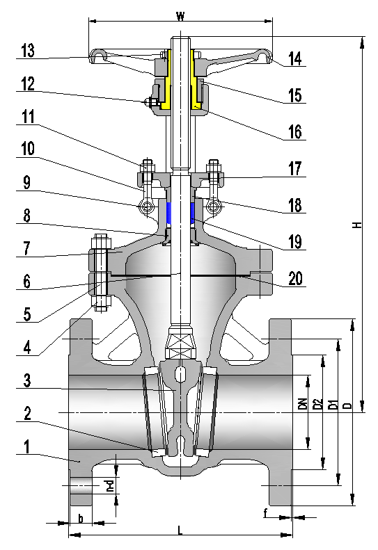
Gate valves are normally operated by a handwheel, a valve T-key (wrench) or an actuator. The wheel is attached to a valve stem and transfers rotational energy to it. During the gate valve opening, the rotation of the handwheel turns the threads of the gate stem into the gate and vice versa for closing. This energy moves the gate valve wedge downwards or upwards.
Generally, gate valves are installed in the areas of a pipeline where they will longer remain open or closed, as they generally require sometime to switch between these two positions.
Dimensions Data
| NPS | 2 | 2 | 3 | 4 | 5 | 6 | 8 | 10 | 12 | 14 | 16 | 18 | 20 | 24 |
| L | 177.8 | 190.5 | 203.2 | 228.6 | 254 | 266.7 | 292.1 | 330.2 | 355.6 | 381 | 406 | 432 | 457 | 508 |
| D | 152 | 178 | 191 | 229 | 254 | 279 | 343 | 406 | 483 | 533 | 597 | 635 | 699 | 813 |
| D1 | 120.7 | 139.7 | 152.4 | 190.5 | 215.9 | 241.3 | 298.5 | 362 | 431.8 | 476.3 | 539.8 | 577.9 | 635 | 749.3 |
| D2 | 92 | 105 | 127 | 157 | 186 | 216 | 270 | 324 | 381 | 413 | 470 | 533 | 584 | 692 |
| b | 14.4 | 16.4 | 17.9 | 22.4 | 22.4 | 23.9 | 26.9 | 28.9 | 30.2 | 33.9 | 35.4 | 38.4 | 41.4 | 46.4 |
| n-d | 4-19 | 4-19 | 4-19 | 8-19 | 8-22 | 8-22 | 8-22 | 12-25 | 12-25 | 12-29 | 16-29 | 16-32 | 20-32 | 20-35 |
| f | 1.6 | 1.6 | 1.6 | 1.6 | 1.6 | 1.6 | 1.6 | 1.6 | 1.6 | 1.6 | 1.6 | 1.6 | 1.6 | 1.6 |
| H | 345 | 387 | 430 | 513 | 583 | 648 | 790 | 935 | 1100 | 1200 | 1330 | 1480 | 1635 | 1935 |
| W | 200 | 200 | 250 | 250 | 300 | 300 | 350 | 400 | 450 | 500 | 500 | 600 | 600 | 650 |

